
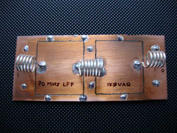
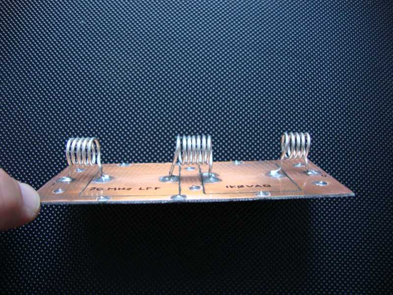
The low pass filter has been used on the output of a 100 W linear amplifier, so this is the maximum power level it has been checked (only on 50 Ohm dummy load), probably the limit should be more. The pictures can explain the construction details, the two 56 pF capacitors have been built cutting a perimeter of 40 * 45 mm square of two copper isles of a double face FR4 PCB board, with a Dremmel tools. It could be possible to realize the two isles using the normal PCB construction method erasing all the copper around the square isles on the top side of the board. The underneath side of the board is the ground connection for both capacitors. The low pass filter has been installed inside the power amp box, but it is possible to build an enclosure for it using peaces of PCB or tinned metal boards, soldering each others and using BNC connectors. For the low pass filter test it has been used a MFJ 59 antenna analyzer and a dummy load, increasing or tightening the coils length to obtain the minimum SWR value; without analyzer it should be possible to measure the maximum TX power level, making the same work on the coils. Hoping I’ve been clear I’m available for any answer, email ik0vaq tin.it
73 Alex IK0VAQ
(Editor: Bo OZ2M tried to make the PCB capacitors for a similar filter but loss was too bad so doorknob capacitors were used instead)