
Modification at your own risk (yes!) of the Microwave Modules MML144/100 Linear to 70 MHz.
First I tested this (second hand) PA on 144 MHz and on 13.8 V it produced max about 60 W! Perhaps the SRF 1397 is not (and never was) up to 100 Watts hi. This PA 144/100/1/2 is old and has no Preamp, so it can be that later produced PA’s have a different PCB Layout….
I modified this 144 MHz PA to 70 MHz using from the “4 Meter Website” both the diagrams and remarks / description (Tnx!) given by SV1DH and GI0GDP. This modification has now become a kind of mixture….
The result is a a 70 MHz PA which has about 10 dB gain and is up to 50 W reasonable Linear and can produce about max 70 W and 10 A at 13.8 V (saturation). The idle current for the PA transistor on TX is about 250- 300 mA (see potentiometer A). Using PSK31 to measure the third order IMD I found IMD-3 at -30 dB (good) at about 15 W output on a normal (slow) Watt-meter and about -20 dB at 20 W output.
The SWR at the input is about 1 to 1 when carefully adjusting the 60 pF Trimmers at No. 2 and No. 3.
Use at the output the 3 coil/2 Doorknob Capacitor Low-pass Filter described by OZ2M or the 3 Coil/ 2 PCB Capacitor Low-pass filter of IK0VAQ. The Doorknob Filter I made here is up to 100 W easily. I saw other filter on the 4 Meter website from G4CJZ and GI0GDP as well.
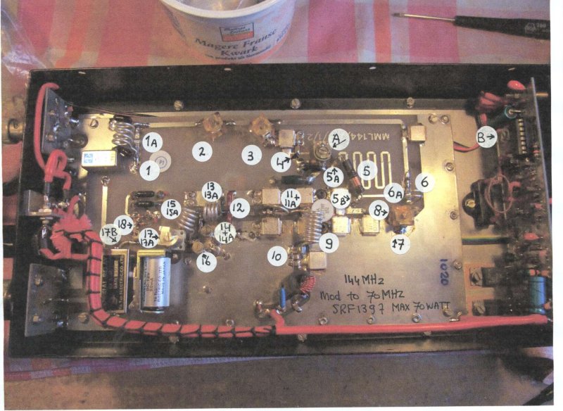
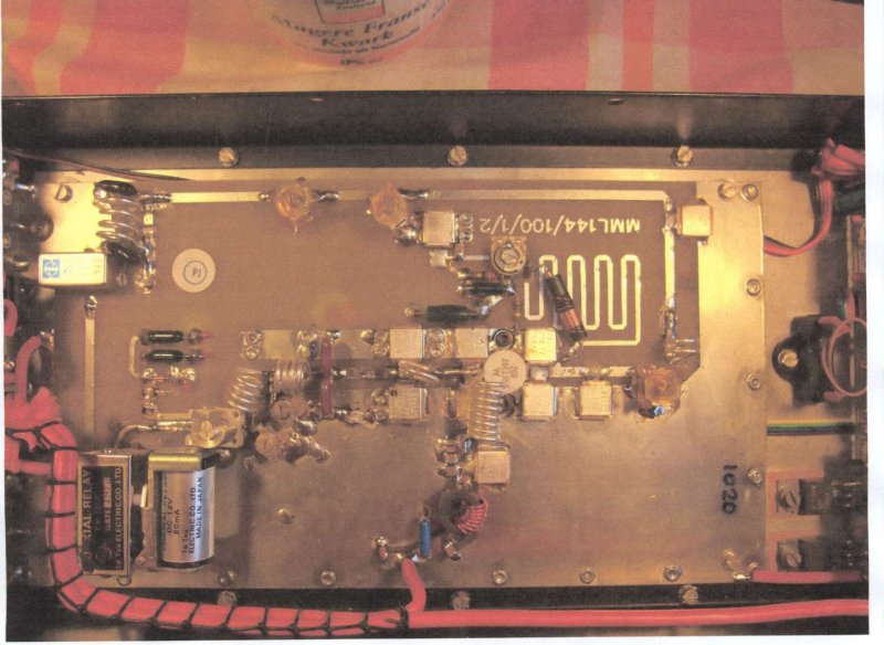
I made two photos of the modified PA with and without numbers at the places of the modifications:There is plenty of room in this PA!
By the way: Before you start take good pictures of the original PA, I did not hi. And while most of the radio-amateurs are human, like me, we can make mistakes so following this description of the modification hereunder is fully at your own risk.
A lot of the original parts can stay in place (hurrah!) , but I removed:
- At 2: remove the 470 pF ceramic capacitor.
- At7 : choice: or remove the original 60 pF trimmer or replace it with a low-loss Teflon trimmer of 60 pF.
- At 14/14A: remove the silver-mica from PCB track to Ground.
- At 17B: remove the 470 pF ceramic capacitor and put a piece of wire in place or leave the 470 pF here.
Now a few changes:
>No. 1A: cut the PCB track located under Coil 1.
>No. 1 = simple Low-pass input filter 50-50 Ohm (Tnx Elsie) with about 20 dB attenuation of 140 MHz.
4 Turns 1.3 mm CuAg 8 mm diameter, long about 17 mm and at both sides 100 pF Silver-mica form the coil to ground. Perhaps SMD capacitors size 1206 and 50 V can also be used here.
>No. 2: 60 pF low Loss trimmer Capacitor, probably Teflon, in series with the track at the place of the original 470 pF capacitor. Remove this one.
>No. 3: 60 pF Low loss trimmer Capacitor from the PCB track to ground.
>No. 4 : 100 nF SMD 1206, 50 volts or better, between ground and the Bias- track to the new 10 uH coil going to the base of the PA transistor.
>No. 5A and 5B: cut the track of the original PCB etched Bias- coil going from the Bias Regulation to the base of the PA transistor.
>No 5: new 10 uH coil, replaces the original PCB coil, made from an old ferrite choke of about 50 uH 1.5 amp, by peeling 2/3 windings of.
>No. 6 A: cut the PCB track under the coil at No. 6.
>No 6: Coil 2 turn 1.3 mm CuAg 8 mm Diameter, long 9 mm
>No. 7: 60 pF Trimmer Capacitor from PCB track to ground
>No. 8: just under and beside (left) of No. 7, a 470 pF SMD 1206 from PCB track to ground or use the removed 470 pF ceramic C.
Leave about 25mm PCB track between Capacitors No.7 / 8 and the base of the PA Transistor .
>No. 9: New collector coil 8 Turns 1.3 mm CuAg 6.5 mm diameter, long 18 mm
>No. 10: 2 x 100 nF SMD 1206 and 2x 4n7 SMD 1206, 50 volts Capacitors from collector-coil No. 9 to ground.
>No 11a: Cut the PCB track between the two sets of the original silver-mica capacitors (at the collector side of the transistor) and place here coil no 11.
>No. 11: Coil 1 Turn 1.3 mm CuAg 1.3mm, about 5 mm long
>Leave between the end of Coil 11 and the capacitors at no 12 about 25 mm PCB track and cut it there at 13 A.
>No. 12: 2 x 180 pF brown Silver-mica 500 volt from PCB track to ground.
>No. 13 A: Cut PCB track under coil No. 13
>No. 13: Coil of 4 turns 1.3 mm CuAg diameter 6.5 mm, long about 10 mm.
>No. 14/14 A: Remove
>No. 14: Small low loss 10 pF Teflon trimmer from coil 13 to ground.
>No. 15 A: cut PCB track under Coil 15.
>No.15 : Coil 4 turns 1.3 mm CuAg Diameter 6.5 mm, long 10 mm
>No. 16 : Small low loss 10 pF Teflon trimmer from coil No. 15 to ground
>No. 17a: cut PCB track under 60 pF air-trimmer.
>No. 17 : 60 pF air-trimmer.
> No. 17 B: Originally there is after this coil No. 17 an 470 pF capacitor place in series with the PCB track. I removed this one and connected both sides of the PCB track with a piece of wire. Perhaps this (original) capacitor can stay.
>No. 18: Not (yet ?) solved, is the VSWR shut-down now, never tested it when the PA was still original though for the 2M Band. Did a short test without a dummy connected at the output, but the shut-down did not work, but the PA is still ok though hi.
>at A: Resistor trimmer for the Idle Bias current. Fully Anti-clockwise first (lowest current without any RF drive) then move the trimmer a bit up clockwise so that there is an increase in current of 250-300 mA (at 13.8 V).
>at B: Resistor trimmer for the Vox-delay. Put it at about 2/3 clockwise, Delay is ok then. When put to much anticlockwise, so with very short delay, I had problems that it would fall off
sometimes….
Success, it looks a lot of work but it is not!